USB-C specifications can look simple on a product page, but procurement decisions are rarely simple. Power rating, data rate, connector orientation, cable length and device compatibility all interact. A buyer does not need exaggerated claims. What helps is a clear way to match the cable or adapter to the job, confirm the operating conditions, and ask for the right evidence before ordering.
What buyers should confirm first
In a real installation, a USB-C cable may be pulled through furniture, mounted inside a panel, connected behind a display, handled by many users, or left in place for long service periods. Those details matter. A product that works on a desk can still be the wrong choice for cable voltage drop and power loss if the connector direction, jacket stiffness or length tolerance is not suitable.
If you are comparing options on the USB-C product catalog, start by separating must-have requirements from nice-to-have features. A reliable RFQ usually includes the device type, target speed, charging requirement, length, connector orientation, expected use environment and any OEM packaging or labeling needs.
Selection checklist for Cable Voltage Drop and Power Loss
| Item to confirm | Why it matters for buyers |
|---|---|
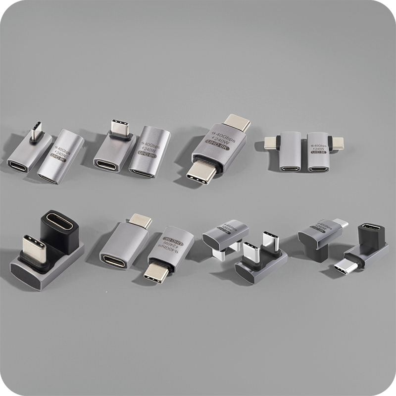
| Connector and orientation | Confirm USB-C male/female direction, straight or right-angle layout, panel-mount or adapter format, and clearance in the final device. |
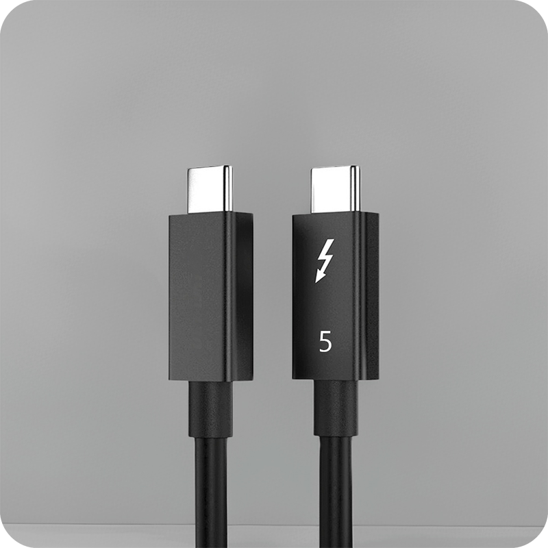
| Data requirement | Match the cable to the real device speed instead of buying from a headline number alone. |
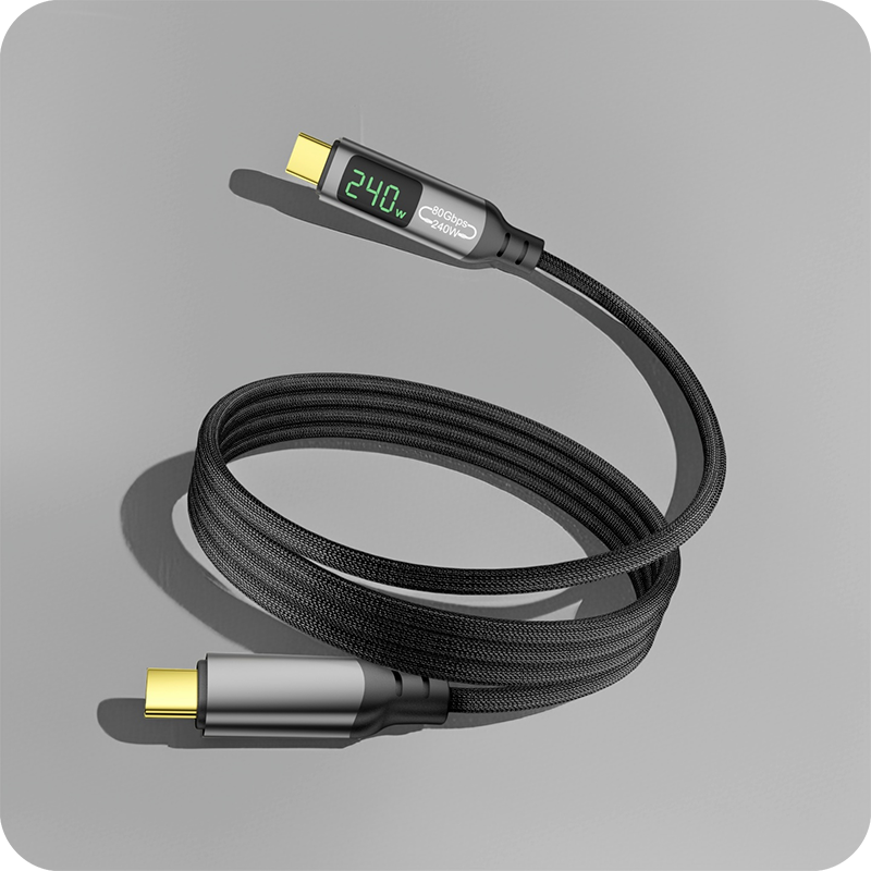
| Power requirement | Check expected charging wattage, current path, conductor design and temperature rise. |
| Length and routing | Review total cable length, bend radius, repeated movement, strain relief and routing space. |
| Evidence before bulk order | Ask for specification sheets, drawings when needed, sample approval, packaging details and relevant test information. |
Where reliability is usually decided
The most common problems are not always dramatic. Many failures come from a connector forced into a tight space, a cable bent too sharply, a run longer than the device can tolerate, or a specification copied from a similar project without checking the actual hardware.
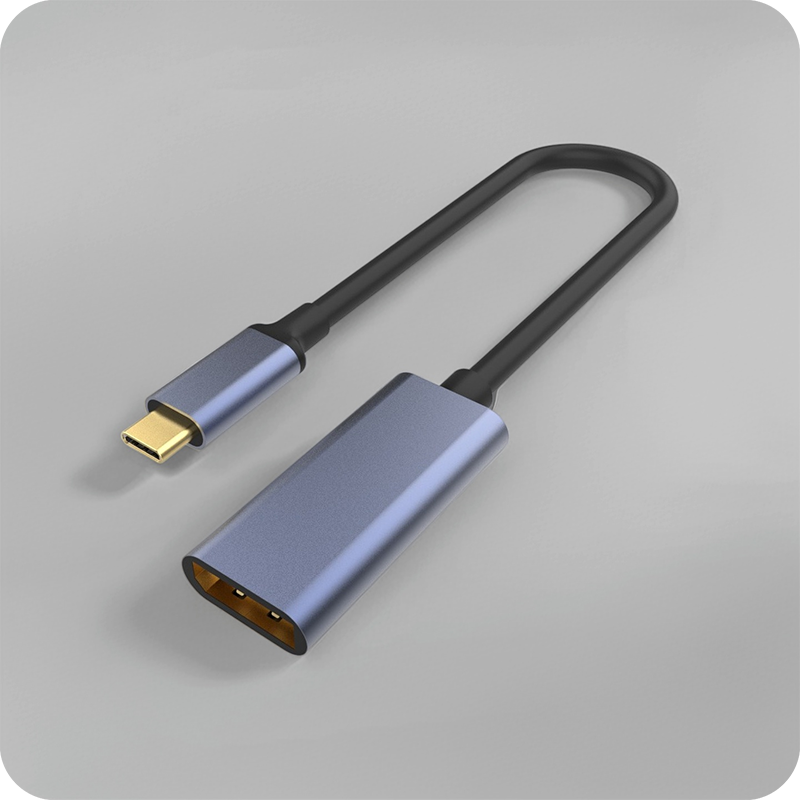
Products such as Double side 20G USB C extension adapter and 240W 20G Type C USB C Female in Moulder Keystone Jack Double side 20G show the type of connector and performance details buyers should review before the final quote. When the application needs another format, compare it with USB3.2 5Gbps USB A To C Female Photography Tools Cable or ask for a recommendation based on the end use.
Mistakes worth avoiding
- Choosing by price before confirming connector direction and installation space.
- Assuming every USB-C cable supports the same power and data features.
- Using consumer desk assumptions for embedded or public-facing installations.
- Skipping sample approval before ordering for a new project.
Questions to include in the RFQ
- What device or system will this USB-C cable connect?
- What data rate and power level are actually required?
- What length, connector direction and jacket flexibility are needed?
- Will the cable be moved often, fixed inside equipment, or exposed to frequent handling?
- Do you need OEM/ODM details such as color, logo, packaging, connector molding or special length?
Practical sourcing note
A good supplier conversation should be specific. Share the device model if possible, the required length, the desired connector direction, the charging or data expectation, and any installation limits. That lets the manufacturer confirm whether a standard item is suitable or whether an OEM/ODM version is a better fit.
For a project quotation, review the catalog and then send the application details through the contact page. Keep the first discussion focused on the real operating conditions rather than only the headline speed or wattage.