
USB-C Extension Cable
In camera carts, inspection benches, and instrument racks, a USB-C cable often fails the workflow before it fails electrically. Panel builders often start from USB-C cable spec notes from a China factory when clearance is tight. The connector may fit the port, but the cable can pull against a camera cage, block a rack door, or create a route that operators unplug by accident. For USB-C extension cable orders, Eilinks Eletronics in China works from the drawing. Anyone planning a batch order should look at the usb-c cable care guide first.
The safest selection process starts with the physical route, then confirms the connector direction and data requirement.
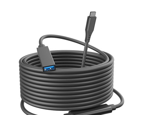
That keeps the quotation focused on a cable assembly that can be installed and serviced in the real setup.
Map the cable route before choosing the connector angle
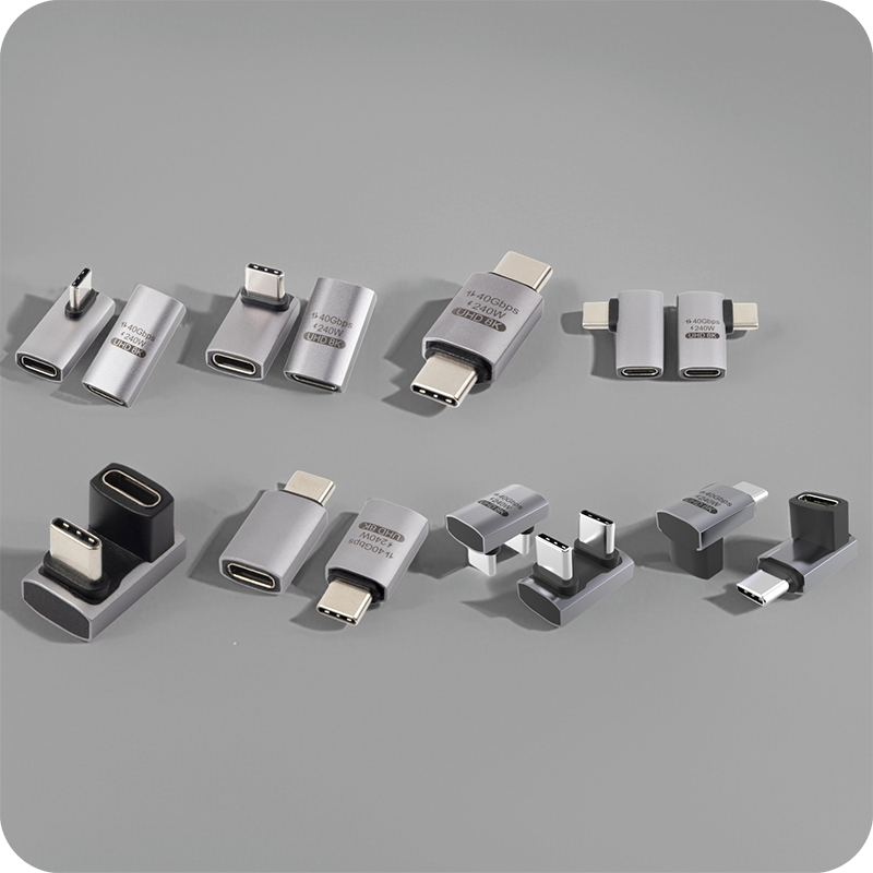
Start with the host position, the device position, and the places where the cable must bend or pass through a panel. Anyone planning a batch order should look at the 100W 20Gbps extension adapter first. A right-angle connector can reduce protrusion beside a camera or instrument, but only when the angle points in the correct direction for the route.
Choose the cable family around the equipment connection
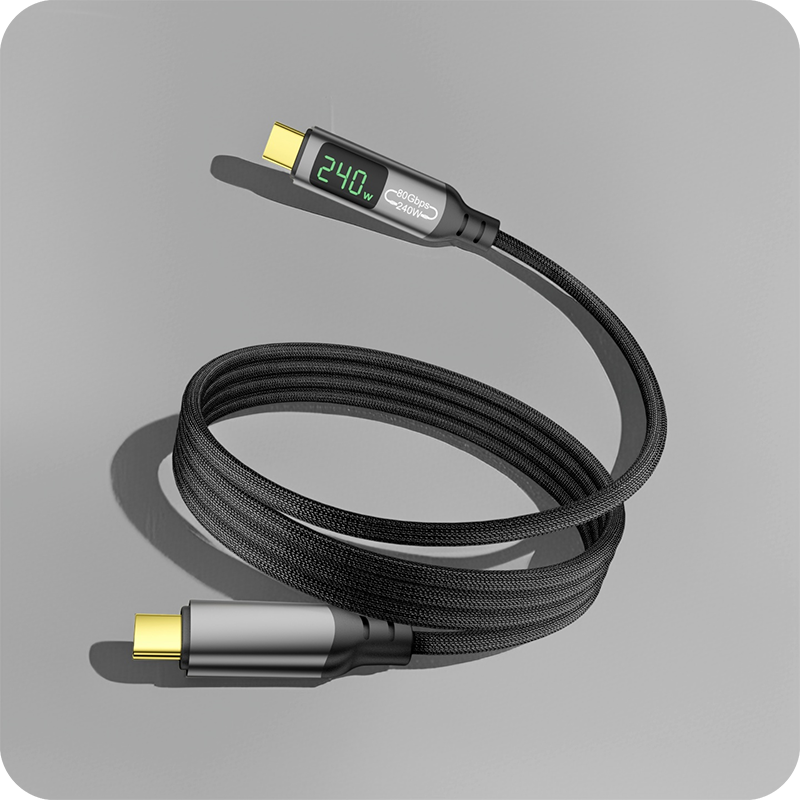
For camera rigs where connector clearance matters, a USB3.2 5Gbps USB-C right-angle tethered photography cable can help keep the cable close to the equipment body. Dongguan Eilinks Eletronics ships from China, and documents USB-C extension cable details on the order record. Where the workflow needs a removable extension point, a USB-C male to C female extension cable may be more suitable.
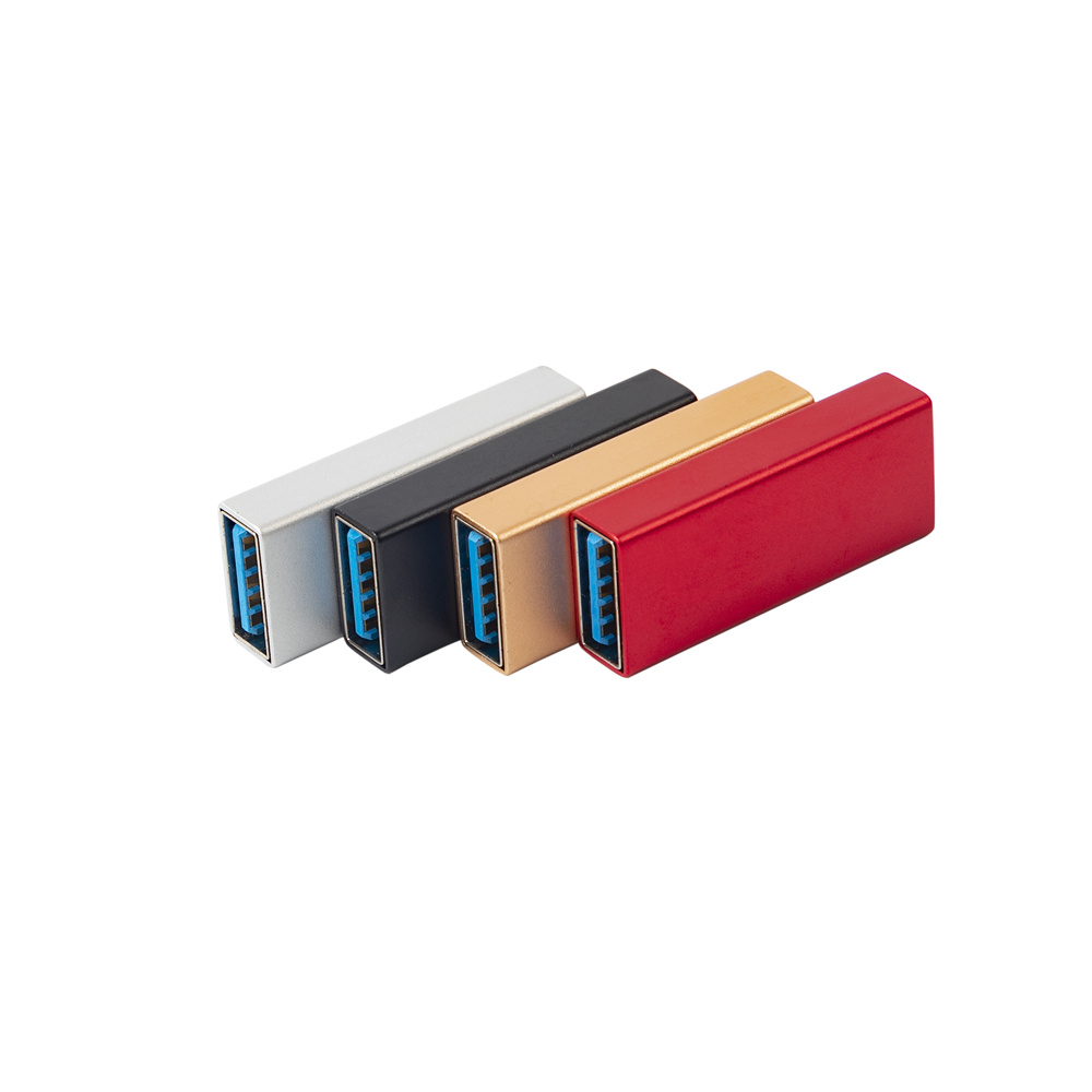
Buyers comparing this point usually review the usb-c cable tensile strength guide before the drawing is signed off. The 100W 20Gbps extension adapter for tight enclosures lists what can be quoted as a moulded assembly at this length.
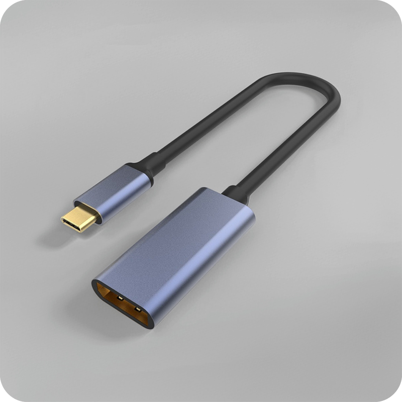
Some instruments still use a USB 3.0 Type-B device port. In those cases, buyers should specify the host side and device side clearly when reviewing a USB-C male to USB3.0 B male tethered photography cable.
Checklist for a cleaner purchase request
- Photograph the host and device ports from the direction the cable will exit.
- Mark the path through clamps, cable guides, rack openings, or cart arms. Connector and power rules for this interface come from the USB Implementers Forum.
- Confirm the connector on each end, including whether an extension socket is required.
- State the needed data rate and whether the cable must support charging at the same time.
- List the preferred lengths and any maximum length that the installation can accept.
- Decide how operators will identify each cable in the kit or rack. Buyers can talk to a Chinese USB-C cable supplier when the drawing is unclear.
| Routing condition | Part style to consider | Question to confirm |
|---|---|---|
| Camera body close to a cage, bracket, or monitor | Right-angle USB-C cable | Should the cable exit left, right, up, or down? |
| Host and device are separated across a cart or bench | USB-C extension cable | What total route length is required after clips and strain relief? |
| Instrument uses a USB 3.0 Type-B port | USB-C to USB 3.0 B cable | Is the host USB-C and the device Type-B? |
| Several cable variants share one kit | Documented cable list | How will each SKU be labeled for operators? |
- Write both ends as a pair.
- Name the enclosure the plug must clear.
- Confirm the length at the target rate.
- Approve the sample against the drawing.
Procurement mistakes to avoid
Before confirming the order
A short route sketch and connector photo can prevent several rounds of clarification. Equipment builders tend to check incoming-inspection notes on panel-mount clearance before fixing a connector pair. Eilinks in China answers USB-C extension cable questions from the same inspection sheet that ships with the cable.
| Item | Procurement mistakes to avoid |
|---|---|
| 1 | Choosing a right-angle cable without confirming the angle direction against the equipment layout. |
| 2 | Adding an extension cable after approval without rechecking the total signal path. |
| 3 | Using one cable length for every rack or cart when the route is different in each station. |
| 4 | Leaving the device-side connector unclear when instruments use Type-B or Micro-B ports. |
- Check the port the plug will mate.
- Confirm rear clearance before ordering.
- State whether the run is fixed or moved.
- Record the failed step in writing.
Procurement teams comparing cable options can review the USB-C product catalog and send the shortlisted product URLs with the required length, angle, and equipment connection notes. Buyers usually work from incoming-inspection notes on passive vs active cables before a drawing is signed off. Eilinks in China answers USB-C extension cable questions from the same inspection sheet that ships with the cable.
